
| INDUSTRIA NAZIONALE CARBURATORI DELL’ORTO Seregno (Milano) Italy – Phone 2341-2342-2343 |
|||||
| SERIES SS DELL’ORTO CARBURETORS For Sport and Racing engines |
 |
||||
| Technical Data | |||||
| Carburetor type | Choke adaptor diameter |
Throttle valve diameter |
Fitting | ||
| Clip | Flange | ||||
| SSI-C | 18 20-22-23 |
31 | ø25.4 ø28.6 |
N/A | |
| SS-A, SSI-A, SSF-A, SSFF-A | 24 25-26-27 28-29-30 |
35 | ø28.6 ø31.7 ø35 |
F 50.8 | |
| SSI-B, SSFI-B | 32 | 38 | ø36 | F 50.8 | |
| SSI-B, SSFI-B | 35 | 42 | ø39 | F 55 | |
| SSI-B | 36-38-40-42 | 48 | ø45 | N/A | |
INDEX
- GENERAL FEATURES
- NECESSARY DATA FOR A SUITABLE CARBURETOR SUPPLY
- INSTRUCTIONS FOR TUNING
- BASE ADJUSTMENT FOR GASOLINE
- USE OF ALCOHOL FUEL
- BASE ADJUSTMENT FOR ALCOHOL
- FIGURE 1 – PROVING DIAGRAM OF THE DIFFERENT RUNNING PHASES
- FIGURE 2 – PROVING DIAGRAM OF THE EXACT LEVEL POSITION
- TABLE A – FOR THE CHOICE OF CARBURETOR DIAMETER
- FIGURE SS-A
- FIGURE SSI-B
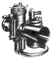
GENERAL FEATURES
Construction in light alloy with anodic protection against the oxidation and hot spraying painting in silver-grey colour.
Clip and flange Fittings
Inserted Choke Adaptor at whole ring and carburation chamber with ininterrupted smooth cylindrical wall.
Throttle Valve in chromium plated special bronze to withstand wear.
Jet Needle with five positions of adjustment, acting in the needle jet.
Needle Jet in high strength special bronze.
Diffuser at great strength multiple elements.
Main Jet flooded in an emulsioning tube, placed under the mixing chamber.
Idle Device: in these carburetors, two are the idle different systems:
- with Interchangeable jet and air adjusting screw fitted on carburetors where the engine needs a high operation sensibility at low speed;
- with variable pilot jet by screw and air fixed, fitted on carburetors for racing engines, where these, according to their use, do not require a meticulous idle.
Mixture strength Control bearing additional air, which brakes the fuel delivery from the needle jet, letting so to enrich (by closing the air valve) the mixture strength if needed, without shutting the choke adaptor section.
Air tube with truncated cone shape in different lengths according to engine requirements.
Allowed fittings. The carburetors of the SS-A series can be fitted with a 15 degrees slant at the most (with throttle valve controlled both in vertical and horizontal plan).
On the contrary the carburetors of the series SS-I, for a special device, can be fitted with larger slants up to 90 degrees (downdraft).
Float Chamber. For the carburetors with choke adaptor from ø 18 to ø 30 mm. fitted on sport engines, stiff float chambers anchored to the carburetor directly are supplied. In this case it is necessary when ordering to point out the induction pipe slant, bearing in mind that 12-26-45 deqrees standard slanting float chambers can be supplied. For racing engines, where their vibrations are of great degree, two types of float chambers are supplied: type SS 1 (larger) for carburetor from ø 32 to ø 42 – type SS 2 (smaller) for carburetor from ø 18 to ø 30.
These float chcunbers have the fuel level at 35 mm. from their lip; when installing they must be fixed so that their level is at the same height of air valve channel center line, as shown on fig. 2.
Banjos for fuel take, single and twin, with the end suitable for direct assembly of rubber pipe and 1/4 gas threaded.
NECESSARY DATA FOR A SUITABLE CARBURETOR SUPPLY
- Engine Make – displacement of each cylinder – 2 or 4 strokes – Number of cylinders.
- Compression Ratio and fuel used.
- Highest Rpm and corresponding power.
- Inner Diameter of induction pipe tube. Induction valve diameter. Section size in mm.² of induction ports – Transfer and exhaust (only for 2 stroke engines).
- Carburetor connection Type to the head or to the cylinder (clip or flange fitting) and its sizes: outside diameter if clip fitting and stud bolt centers if flange fitting.
- Eventual Slant to which the carburetor will be subjected.
- If normal or remote Float Chamber wanted; top or bottom feed and banjo sizes for the connection to the fuel pipe.
- In case of normal float chamber, it is necessary to state if right or left is wanted, stating it by looking the carburetor body from the air tube side.
- Air tube wanted: if long or short one.
For the choice of the carburetor to set up on the different engines please see table A.
INSTRUCTIONS FOR TUNING
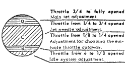
IDLE ADJUSTMENT
(Throttle valve opening corresponding to the section A – Fig. 1)
It is necessary first of all to bear in mind that this adjustment must be established always when the engine has reached its normal running temperature.
- In the first idle system,, where is subsisting the replacing jet and the air adjusting screw, you must operate on this air screw in order to obtain a correct carburation, bearing in mind that by tightening it the mixture strength is enriching, while by unscrewing it the mixture strength is weakening.
- In the second system, where is subsisting the variable screwed pilot jet and the fixed air, the wished engine running will be obtained by operating only on the screw which adjusts the fuel passage; the mixture strength will weaken by tightening this screw and will enrich by unscrewing it.
This second idle system, although it is not exact and sensitive like the first one (suitable to particular uses and engines as told in the general features) allows a better and quicker mixture strength change; it favours therefore easy corrections of carburation also in the passage runnings and necessary easy enrichments in case of alcohol feed.
With both the idle systems is always advisable to adjust the mixture strength at the slowest runnings, rather about the rich, in order to have then clean passages and pickups without hesitation.
FIRST PASSAGE ADJUSTMENT
(Throttle valve opening corresponding to the section B – Fig. 1).
When obtained a satisfactory idle adjustment, one becomes to the choice of the suitable throttle valve for the intermediate runnings, proceeding as follows.
- If opening gradually the throttle valve for a space corresponding to the part B – fig. 1 the engine running is normal, it means that the throttle valve is suitable.
- If the engine is inclining to fall or it gives backfires for weaken mixture, it means that the fitted throttle valve has a cutaway too high and it is necessary to replace it with another one of lower size.
- If the engine instead is emitting black smoke at the exhaust or it is giving irregular explosions with a heavy running, it means that the fitted throttle valve has a cutaway too low and it is necessary to replace it with another one of upper size.
JET NEEDLE ADJUSTMENT
(Throttle valve opening corresponding to the section C – Fig. 1).
In order to have the possibility to adjust the jet needle there are on it 5 grooves or holes (the numeration is starting from the top as follows: 1-2-3-4-5). The jet needle checks the carburation for a throttle valve opening corresponding to the section C – Fig. 1.
If the mixture seems to be weak, the needle must be moved upwards one or two grooves so as to allow a larger flow of fuel at the exit of the needle jet.
If instead the mixture appears to be reach, the opposite must be done, by lowering the needle a few grooves (or holes where existing).
The average position of the jet needle is generally established by us at the third groove (or hole).
MAIN JET SIZE
(Throttle valve opening corresponding to section D – Fig. 1).
The influence of the main jet is especially felt in the throttle valve opening corresponding to section D – Fig. 1.
It is therefore in this field that it is necessary to operate in order to establish if the main jet fitted is the most suitable one, and precisely:
If fully opening the gas, the engine begins to turn over with difficulty and instead of increasing in speed,it does not change or even loses and tends to backfire, and if by closing the mixture control piston, a distinct improvement in running is noted, this indicates that the mixture is too weak. In this case the main jet must be replaced by others of the next sizes up until the one, which gives the correct result, is found.
If the throttle valve is fully turned on, and the engine gives a muffled sound from the exhaust or is missing explosions with emission of black smoke, and by closing the air valve the defect increases, this indicates too rich a mixture. In this case it is necessary to replace the fitted main jet by others of the smaller sizes until the one, which gives the correct result, is found.
A correct carburation at high speed must be obtained at completely opened air valve.
It must be born in mind that it is advisable to use the size of the main jet which will have given the best result in power or highest speed but that will have however kept the engine at a temperature of safety.
Exact main jet = normal engine temperature
Small main jet = higher engine temperature
Large main jet = lower engine temperature
Only following scrupolously the above instructions and using a sensibility at the highest point when effecting the tests on road and at the brake, one may arrive at a perfect adjustment of the carburetor and therefore at the best performance of the engine itself.
As approximate adjustment data please see at the adjustment key for gasoline.
BASE ADJUSTMENT FOR GASOLINE
| Carburetor type | Throttle valve | Jet needle | Needle jet | Main jet | Pilot jet |
|---|---|---|---|---|---|
| SSI-C 18-20-22-23 |
Cat. N° 1916 70 |
Cat. N° 2289 R2 at 3 groove |
Cat. N° 1805 260 |
Cat. N° 1126 85-95-105-110 |
Cat. N° 1159 50 |
| SS-A, SSI-A, SSF-A, SSFF-A 24-25 26-27-28 29-30 |
Cat. N° 2384 90 100 100 |
Cat. N° 1824 M7 at 3 groove M13 at 3 groove M13 at 3 groove |
Cat. N° 1805 260 265 270 |
Cat. N° 1126 115-120 125-130-135 140-145 |
Cat. N° 1159 50 50 50 |
| SSI-B, SSFI-B 32 |
Cat. N° 3466 110 |
Cat. N° 1141 N1 at 3 groove |
Cat. N° 1121 315 |
Cat. N° 1126 155 |
|
| SSI-B, SSFI-B 35 |
Cat. N° 3686 120 |
Cat. N° 1900 P1 at 3 groove |
Cat. N° 1121 320 |
Cat. N° 1126 170 |
|
| SSI-B 36-38 40-42 |
Cat. N° 4545 130 150 |
Cat. N° 2470 S1 S1 |
Cat. N° 1121 325 330 |
Cat. N° 2475 180-200 220-240 |
USE OF ALCOHOL FUEL
All our carburetor types of the series SS-A and SS-I are very well suitable also for running with alcohol fuel provided that their general adjustment is revised in the following points.
- Throttle valve
The size generally used for normal super fuels must be replaced by one immediately lower. - Needle jet
A needle with calibrated hole of higher size must be fitted, bearing in mind that the increase of this hole will be directly proportional to the alcohol quantity contained in the fuel that one is intended to use. - Jet needle
For fuels with much than the 50% of alcohol end up to the use of methanol, it will be necessary else to replace the needle used for super fuels by one with a thinner end, foreseen by us for this use. The average position advised by us for alcohol fuels is at the 4th groove (or hole). - Main jet
A main jet oversized from 25 to 50 points about must be fitted according to the carburetor diameter and to the alcohol percentage of the new fuel. - Pilot jet
Also for the running in the idle area it will be necessary increase the mixture strength, operating as follows.
- Idle with rechangeable jet and air adjusting screw
for fuels with alcohol up to 50% it will be enough to tighten the air screw, in comparison to the adjustment used for super fuels, just to its complete tightening.
for fuels with alcohol over the above percentage it will be necessary also to replace the pilot idle jet by a larger one from 5 to 15 points and adjust comparatively the air screw. - Idle with variable screw and air fixed
with the idle system it is enough to open the screw at pleasure just when a correct idle running is obtained and in the first throttle valve openings.
Of course all these instructions are not rigorously fixed but partly entrusted to the judgment and to the sensibility of the experimenter who only by meticolous tests and exactly knowing the features of his engine and of the fuel used, will have the possibility to realize a perfect carburetor adjustment.
As approximate adjustment data please see at the adjustment key for alcohol.
BASE ADJUSTMENT FOR ALCOHOL (upper the 50%)
| Carburetor type | Throttle valve | Jet needle | Needle jet | Main jet | Pilot jet |
|---|---|---|---|---|---|
| SSI-C 18-20-22-23 |
Cat. N° 1916 60 |
Cat. N° 2289 R4 at 4 groove |
Cat. N° 1805 275 |
Cat. N° 1126 130-135-140-145 |
Cat. N° 1159 60 |
| SS-A, SSI-A, SSF-A, SSFF-A 24-25 26-27-28 29-30 |
Cat. N° 2384 70 80 90 |
Cat. N° 1824 M3 M3 M3 |
Cat. N° 1805 280 280 280 |
Cat. N° 1126 150-155 160-170-180 190-200 |
Cat. N° 1159 70 70 70 |
| SSI-B, SSFI-B 32 |
Cat. N° 3466 80 |
Cat. N° 4338 N2 |
Cat. N° 1121 350 |
Cat. N° 1126 220 |
|
| SSI-B, SSFI-B 35 |
Cat. N° 3686 90 |
Cat. N° 4339 P2 |
Cat. N° 1121 360 |
Cat. N° 1126 250 |
|
| SSI-B 36-38 40-42 |
Cat. N° 4545 100 110 |
Cat. N° 2470 S8 S8 |
Cat. N° 1121 370 380 |
Cat. N° 2475 250-280 310-340 |
Proving diagram of the different running phases.
Proving diagram of the exact level position.
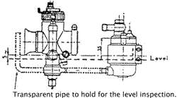
Table A – for the choice of carburetor diameter |
|||
| Cylinder displacement | Choke adaptor diameter for the undermentioned motorcycle classes | ||
|---|---|---|---|
| Sport | Supersport | Racing | |
| 125 cc 4 st. | 20 | 22 | 28 |
| 125 cc 2 st. | 22 | 24 | 30 |
| 175 cc 4 st. | 24 | 26 | 30 |
| 175 cc 2 st. | 26 | 28 | 32 |
| 250 cc 1 st. | 26 | 28 | 32 |
| 250 cc 2 st. | 28 | 30 | 35 |
| 350 cc 4 st. | 28 | 30 | 35 |
| 500 cc 4 st. | 30 | 32 | 38 |
| 600 cc 4 st. | 32 | 35 | 40 |
| 750 cc 4 st. | 35 | 38 | 42 |
Proving section of SS-A carburetor with idle system of rechangeable jet and normal float chamber.
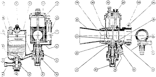
1) Fixing float chamber top screw – 2) Tickler – 3) Float chamber cap – 4) Mixing chamber top – 5) Mixing chamber cap – 6) Carburetor body – 7) Air valve – 8) Air valve channel – 9) Jet holder – 10) Holding bolt for float chamber – 11) Main jet – 12) Filter – 13) Banjo nut – 14) Banjo – 15) Needle seating – 16) Float needle – 17) Float – 18) Float chamber body – 19) Throttle valve – 20) Choke adapter – 21) Throttle stop screw – 22) Throttle cable adjuster – 23) Outlet clip – 24) Outlet cable clip – 25) Idle second hole – 26) Idle air channel – 27) Air adjusting screw – 28) Idle first hole – 29) Pilot jet – 30) Idle fuel channel – 31) Jet plug – 32) Neelde jet – 33) Spray tube – 34) Jet needle – 35) Air tube
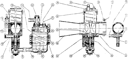
Proving section of SSI-B carburetor with idle system of rechangeable jet and remote float chamber SS-I.
1) Jet needle – 2) Float – 3) Banjo – 4) Banjo nut – 5) Jet needle seating – 6) Jet needle – 7) Tickler – 8) Rocking lever – 9) Clamp ring for float chamber – 10) Clamp ring gasket for float chamber – 11) Float chamber body – 12) Petrol outlet connection – 13) Banjo – 14) Carburetor body – 15) Choke adaptor – 16) Air valve channel – 17) Air valve – 18) Throttle valve – 19) Mixing chamber top – 20) Throttle cable adjuster – 21) Throttle stop screw – 22) Outlet clip – 23) Outlet clip pin – 24) Pilot adjuster – 25) Pilot needle insert – 26) Idle air channel – 27) Idle fuel channel – 28) Idle outlet channel – 29) Needle jet – 30) Main jet – 31) Banjo nut – 32) Jet holder – 33) Air channel for emulsioning – 34) Air tube – 35) Spray tube – 36) Mixing chamber cap